HomeCuplock Formwork System for Slab Shoring
Cuplock Formwork System for Slab Shoring
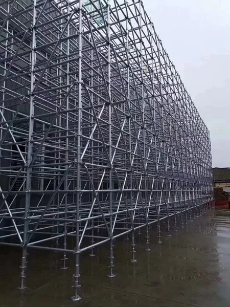
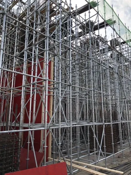
Cuplock formwork supports slab formwork with a grid of standards, ledgers, and U-heads. The system is assembled from standard components without loose fittings.
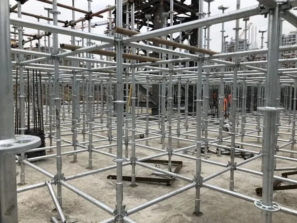
Cuplock Under Slab Formwork: Grid, Lifts, U-heads
Cuplock standards are placed on base jacks at the required grid spacing. Ledgers connect standards at cup positions every 500 mm. The grid forms a stable support structure for slab formwork.
Lifts are determined by the clear height and slab thickness. U-head jacks are placed on top of standards. U-heads carry timber or steel bearers that support the formwork surface. The assembly is adjusted with jack nuts at the base and top.

Engineer Inputs for Cuplock Formwork
| Slab thickness | Concrete slab thickness determines dead load and formwork pressure. Provide the design slab thickness. |
|---|---|
| Clear height | Distance from floor to slab soffit sets standard lengths and lift configuration. Include any beams or drops. |
| Grid preference | Bay spacing and ledger lengths control component quantities. State preferred grid or let VANHN propose one. |
| Quantities | Area to be shored and pour sequence drive the bill of materials. Send overall dimensions and phasing. |
Adjustable steel props
| Part | Tube diameter | Finish |
|---|---|---|
| Outer tube | 48 / 56 / 60 mm | Hot-dip galvanized, painted or powder coated |
| Inner tube | 40 / 48 mm | Same as outer tube |
| Adjustment | Threaded collar with G-pin | - |
Closed and extended heights are made to order. Load data is issued with the quotation.
Send a technical inquiry
Grid, clear height and quantities are enough. We return dimension sheets and load data for your case.
- Made in our own plant, 100,000 m², founded 2016
- Hot-dip galvanized, painted or powder coated
- Reply within 24 hours